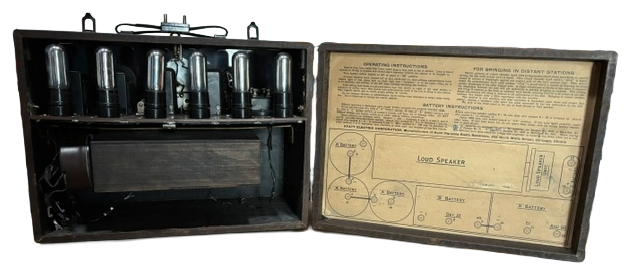
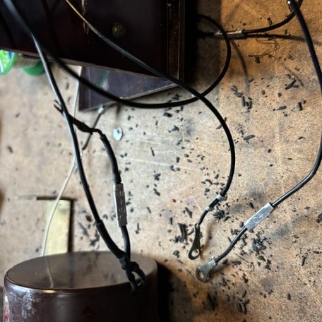
One of the first things I noticed on inspection was the deteriorating insulation on the battery connection wires. That will need to be addressed. But first I need to get the chassis out. That's becoming a challenge. There are 3 screws on each side. The bottom 2 are attached to the bracket that holds the speaker in place. The top 2 attach to the main board, but I can't remove the board yet-there must be another attachment. I found 2 thin slats on either side holding the front panel in place. Once removed, I needed to unscrew the nut holding the antenna connector to the top of the case and then everyhing slid out.
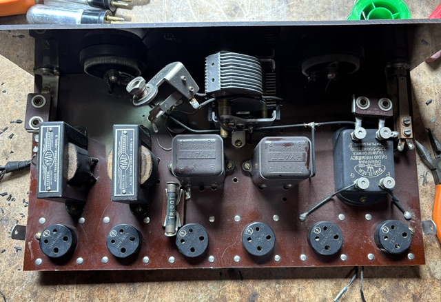
I tested the tubes - 3 good, 3 bad. I next tested the 2 transfomers. 1 was good, the other had a bad secondary. That will be R/C coupled.
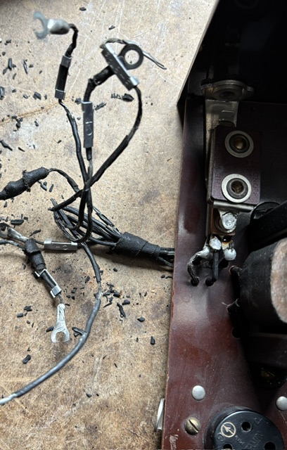
The biggest issue is the battery wires-the insulation is completely falling off. I'd like to retain the small clips that indicate what the voltages are and put them on the new wires. It will be tedious, but necessary.
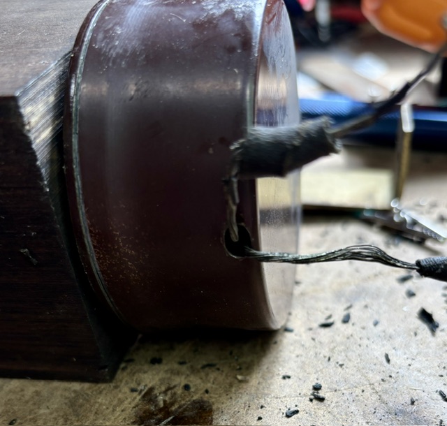
I can't completely replace the wires going into the speaker driver-there is no way to open it. I'll just cut the connections and slide some heat shrink tubing over them and hope I can reach all the way in.
 Much better, but now I've found another problem
I discovered another transformer, an RF transformer, and one side is open.
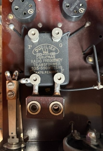
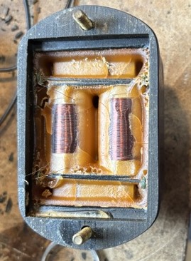
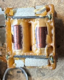
I found some information on the internet where others have dealt with this. It's encased in wax. I tried unwinding the bad coil a loop, cleaning the leads and retesting it, but apparently the problem is deeper in, and I may have to rewind it. I will need to take it completely apart and try not to damage the good coil.
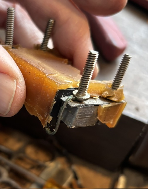
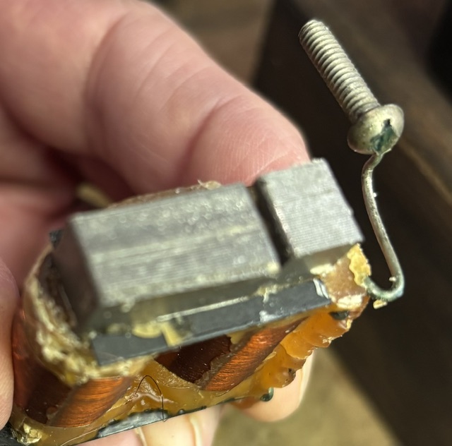
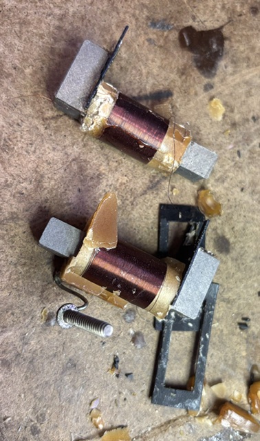 Good news, bad news
Good news is that the break is on the end of the coil, so I won't have to rewind it. Unfortunately, I broke the connection of the good coil, so they'll both need to be reconnected. That was a very tedious and eye straining process. It is 40 gauge wire so it can't be soldered to the stud legs or it would melt from the heat. I wound the wires a few times around the legs after carefully sanding the enamel off to get a good connection. No longer having the wax to hold things together, I dangled it into the case until I was able to get the studs to line up with the holes. Not fun. I then attached the nuts loosely and then tightened them while holding the legs of the studs so they wouldn't turn too much. I continually tested the connections to make sure they stayed solid. I replaced the bottom plate and rewired it back into the set.
Onward to the bad audio transformer.
I'll be using the same R/C bypass setup I used for the ERLA 271, sold by Tony's Capacitor Corner. It's very convenient.
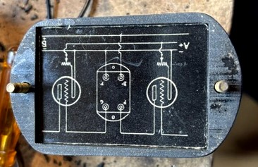
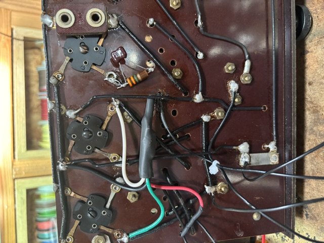
First attempt; 6 good tubes, hooked up to ARBE III , and antenna - no sound. There is no schematic for this, so I'll have to do some troubleshooting. One odd thing is a hookup for 67 1/2 volts and another that just says DET. I hooked the DET to 45 volts. Strangely I am getting an odd weak radio signal that's not tunable.
I decided to test the tube voltages. I was having a problem getting a good connection with my probes, so I decided to make a test socket from the base of one of the bad tubes.
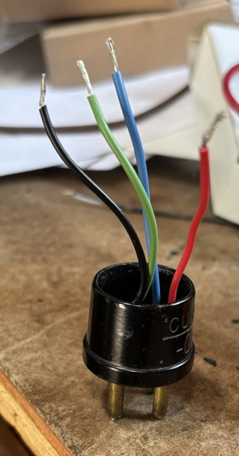 I found a few of the tubes with bad socket connections. I used a needle file and Deoxit to clean them up.
I found that the only tubes getting 90 volts were the audio tubes. The others, with the exception of the detector, were around 70 volts (67 1/2).
It's now working. The audio transformer that I thought had a bad secondary, also had a bad primary. I had to adjust my R/C bypass to account for that. I also changed out the capacitor/grid leak combo at the detector from 900pf and 9 megohm to 250pf and 3.3 Megs.
 Now it's just a matter of putting it all back together.
Finished - 5/30/2026